Meet MITCH

I began my involvement with the MITCH flight computer project when it was still under Purdue Space Program Solids (PSPS) in fall 2019. The basic goals of this project was to complete a student researched and designed (SRAD) flight computer to fly with the PSPS rocket at the Spaceport America Cup in 2020.
After Covid-19, there was no Spaceport America Cup 2020. There was also no launch in 2021 as Spaceport America moved virtual for that year. Currently, the MITCH flight computer project is under Purdue Space Program High Altitude, and is being developed to work at altitudes reaching and exceeding the Kármán line. Below I have listed specific boards I designed over the past two years.
MITCH v21.1

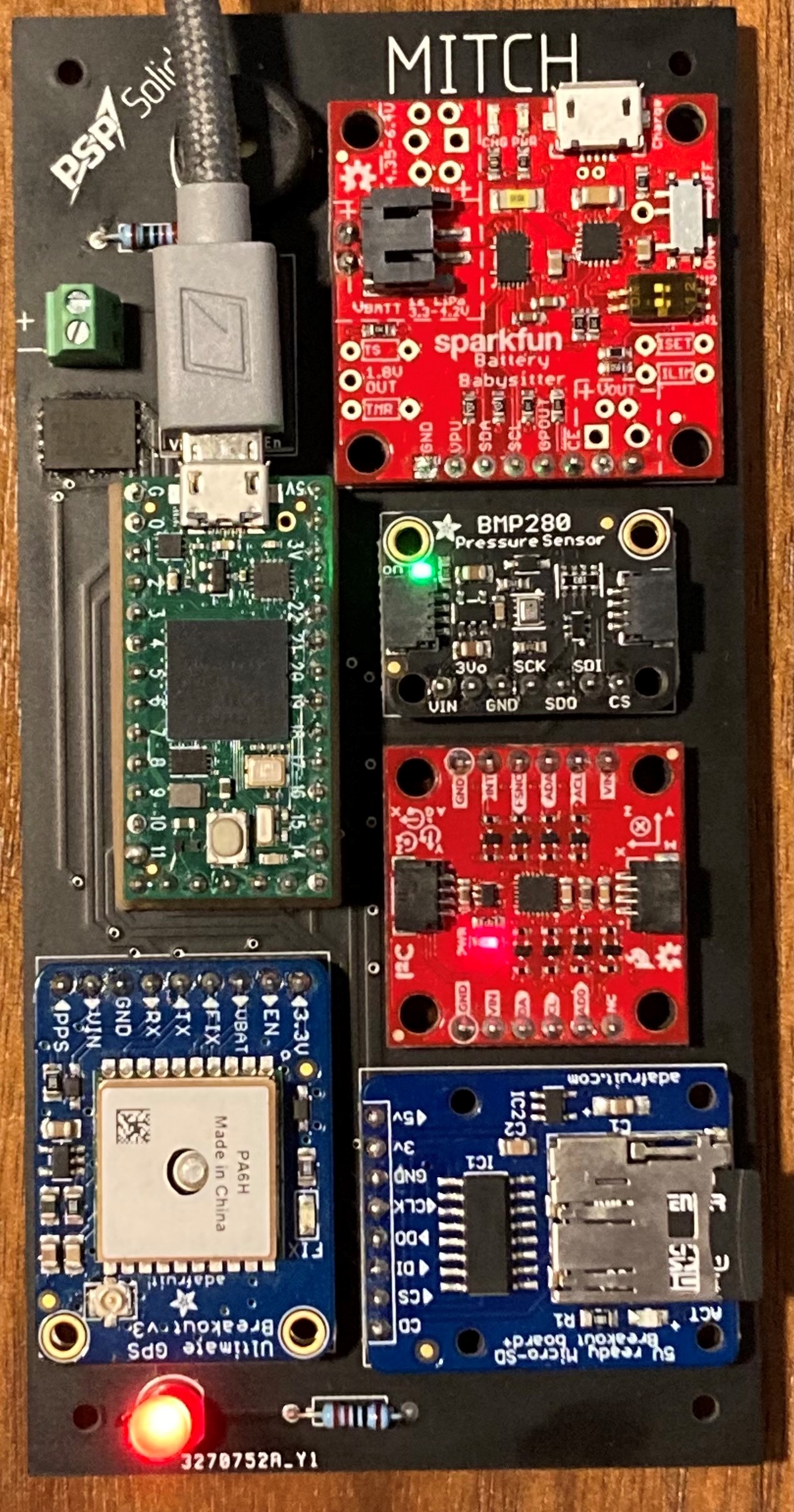
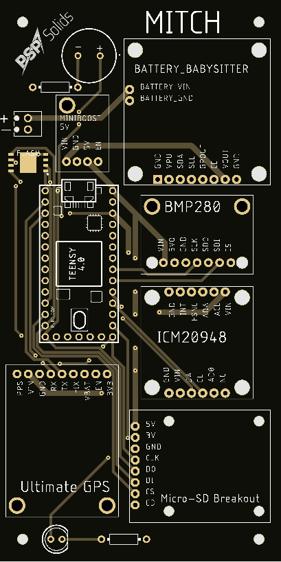
This board was the first fully assembled and functioning MITCH flight computer. While completely passive during flight, MITCH v21.1 is able to collect sensor data from its onboard IMU, GPS, and barometer. As of writing this, the flash storage chip is not functional most likely due to software issues. However, the backup SD card successfully records all raw sensor data. MITCH is controlled by a Teensy 4.0 microcontroller programmed with a flight script I wrote in the Arduino IDE. MITCH is also equipped with a red LED and Buzzer for debugging and power on confirmation. This board was also my first attempt at using a reflow oven (flash chip). I am immensely proud of this computer and I plan to launch a second test of it on my L2, Enlil, in the coming weeks (for info on the first test launch, please go to the DUMBO I page). Additionally, I plan to integrate MITCH’s code with RTOS in the next few weeks, time permitting. This board has greatly increased my confidence in electronics and engineering in general, and I look forward to building more robust versions of this computer. Some lessons I’ve learned from this board is that I need to consider manufacturing more during my design phase. For example, without a standoff the micro USB connector to the teensy microcontroller would be blocked by the placement of the boost converter. Additionally, the red LED must be de-soldered if one needs to replace the coin cell battery located below the GPS board.
Power Systems Prototype 2.0

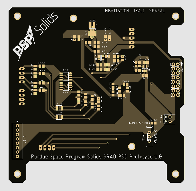
This board was the second iteration of the power systems and parachute deployment prototyping boards. As you might have noticed, this prototype doesn’t list parachute deployment in the title. Based on the lessons learned from the last board, I decided with the other board designers that it would be best to simplify the board to power management and figure out parachute deployment circuitry in a future design. This board builds on my understanding of power circuitry and relies much less on other commercial designs like Prototype 1.0. Unfortunately, due to time constraints we did not manufacture this board and it remains a design. I did learn quite a bit about reading datasheets and good circuit practices from this board though, and that carried over into my future projects.
Power Systems and Parachute Deployment Prototype 1.0

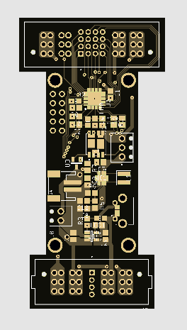
This board was designed to be a power management system, as well as house the circuits required for deploying rocket parachutes. With a 1s Lipo connected, it would provide 3.3V and 5V to the sensors and processing prototyping boards. It also had overdraw logic and deployment circuitry heavily based on other commercial systems like the Sparkfun Battery Babysitter and the Altus Metrum Telemetrum v3.0. Testing of this board revealed it did not provide power. This first prototype taught me that I cannot effectively use circuits I don’t understand. Debugging this board was a nightmare because this was one of my first electronic projects and I didn’t understand it well thanks to my heavy reliance on commercial designs. Since similar issues occurred with its sister boards (sensors and processing), this board was scrapped.